 Tonkee Machinery Logo


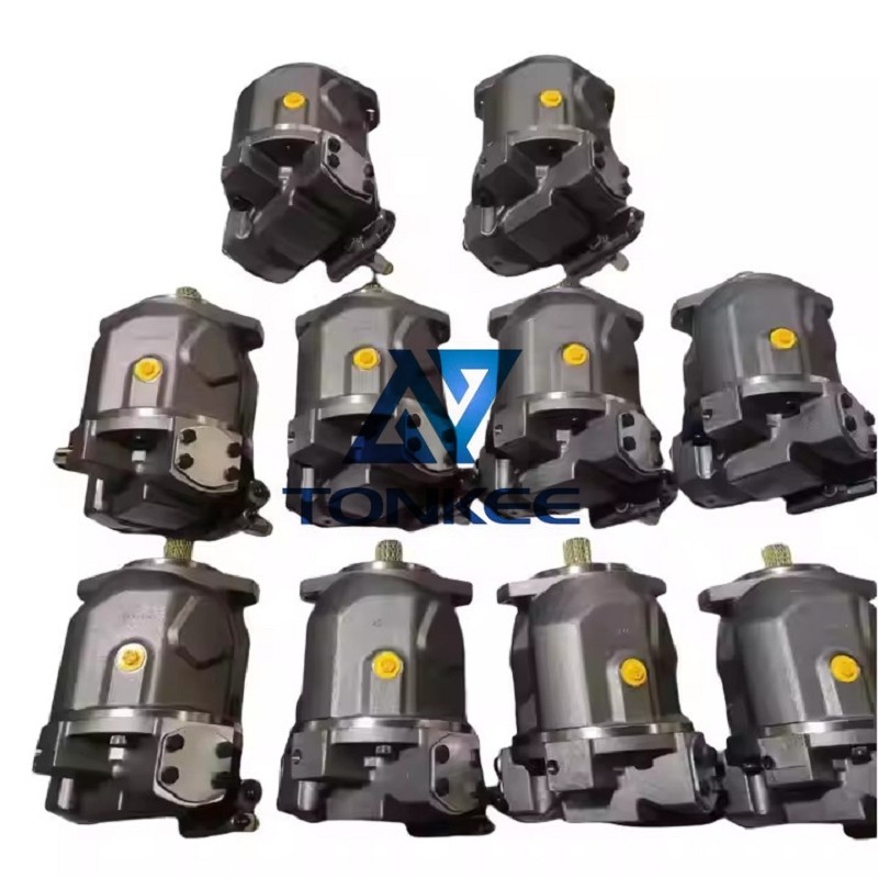
1. What is the detailed interpretation of the two models “A10VSO45DFR/31L-PSA12N00” and “A10VSO10DR/52R-PPA14N00”?
| Model Segment | A10VSO45DFR/31L-PSA12N00 Explanation | A10VSO10DR/52R-PPA14N00 Explanation |
|---|---|---|
| A10VSO | Series Identifier: Axial Piston Variable Displacement Pump (Industrial-grade, high-pressure design for mobile and stationary hydraulic systems) | Same as left (Consistent series definition for A10VSO hydraulic pumps) |
| 45 / 10 | Nominal Displacement: 45 cm³/rev (cubic centimeters per revolution, indicating fluid volume displaced per shaft rotation) | Nominal Displacement: 10 cm³/rev (Smaller displacement for low-flow, precision hydraulic systems) |
| DFR / DR | Control Type: D = Dual control (pressure + flow); FR = Hydraulic pilot control with pressure compensation (automatically adjusts flow based on load) | D = Dual control (pressure + flow); R = Hydraulic pilot pressure control (basic pressure adjustment function) |
| 31L / 52R | Mounting & Rotation: 31 = SAE 3-bolt flange (complies with SAE J744 Class 3); L = Counterclockwise rotation (viewed from shaft end) | 52 = SAE 5-bolt flange (complies with SAE J744 Class 5); R = Clockwise rotation (viewed from shaft end) |
| PSA12N00 | Configuration Code: PS = Integrated pressure relief + sequence valve; A12 = Relief valve setting (280 bar); N00 = Standard factory calibration (no custom modifications) | PPA14N00 = PP = Integrated pressure relief valve; A14 = Relief valve setting (315 bar); N00 = Standard factory calibration (no custom modifications) |
2. What are the core technical parameters of the two pumps?
| Parameter | A10VSO45DFR/31L-PSA12N00 | A10VSO10DR/52R-PPA14N00 |
|---|---|---|
| Nominal Displacement | 45 cm³/rev | 10 cm³/rev |
| Maximum Working Pressure | 350 bar (5075 psi) | 350 bar (5075 psi) |
| Rated Working Pressure | 315 bar (4568 psi) | 315 bar (4568 psi) |
| Maximum Speed | 2600 rpm | 3600 rpm |
| Minimum Speed | 500 rpm | 500 rpm |
| Oil Viscosity Range | 10 – 400 mm²/s | 10 – 400 mm²/s |
| Recommended Oil Temperature | -20°C to +90°C (-4°F to 194°F) | -20°C to +90°C (-4°F to 194°F) |
| Oil Filtration Requirement | ≥ 10 μm (ISO 4406 Class 16/13) | ≥ 10 μm (ISO 4406 Class 16/13) |
| Shaft Diameter | 35 mm (1.38 in) | 20 mm (0.79 in) |
| Mounting Standard | SAE J744 (3-bolt flange) | SAE J744 (5-bolt flange) |
| Inlet/Outlet Port Size | Inlet: G1 1/4″, Outlet: G1″ | Inlet: G3/4″, Outlet: G1/2″ |
| Dry Weight | Approx. 32 kg (70.5 lbs) | Approx. 8 kg (17.6 lbs) |
| Volumetric Efficiency | ≥ 95% | ≥ 95% |
| Mechanical Efficiency | ≥ 92% | ≥ 92% |
3. What are the key differences between the two models?
- Displacement & Flow Capacity: The A10VSO45DFR (45 cm³/rev) has 4.5 times the nominal displacement of the A10VSO10DR (10 cm³/rev), making it suitable for medium-flow systems (e.g., small excavators), while the A10VSO10DR is ideal for low-flow, precision applications (e.g., hydraulic actuators).
- Control Function: The A10VSO45DFR uses DFR control (pressure-compensated) for energy-efficient flow adjustment, while the A10VSO10DR adopts basic DR pressure control for simple pressure-regulated scenarios.
- Mounting & Rotation: The A10VSO45DFR features a 3-bolt flange (31) and counterclockwise rotation (L), while the A10VSO10DR has a 5-bolt flange (52) and clockwise rotation (R)—the flange difference affects installation compatibility, and rotation direction must match system requirements.
- Pressure Relief Setting: The A10VSO45DFR’s relief valve is set to 280 bar, while the A10VSO10DR’s is set to 315 bar, adapting to different system pressure protection needs.
- Size & Weight: The A10VSO10DR (8 kg, 20 mm shaft) is much smaller and lighter than the A10VSO45DFR (32 kg, 35 mm shaft), suitable for space-constrained equipment.